Table of Contents
What is Flowchart in Programming?
An idea expressed in a picture or diagram is preferred to text form by people. In certain situations, the algorithm may be difficult to follow, as it may contain complex tasks and repetitions of steps. Hence, it will be better if it could be expressed in pictorial form.
The pictorial representation of an algorithm with specific symbols for instructions and arrows showing the sequence of operations is known as flowchart.
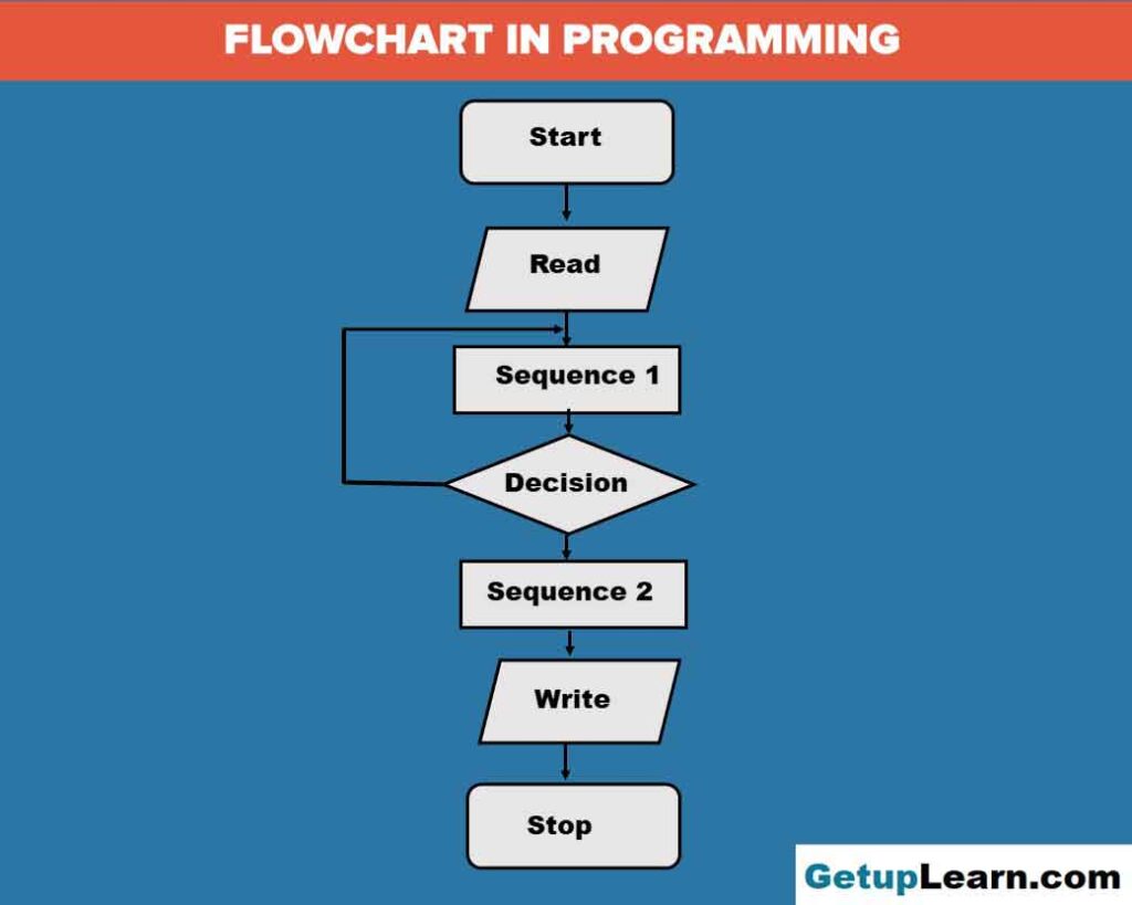
Table of Contents
It is primarily used as an aid in formulating and understanding algorithms. Flowcharts commonly use some basic geometric shapes to denote different types of instructions. The actual instructions are written within these boxes using clear and concise statements.
These boxes are connected by solid lines with arrow marks to indicate the flow of operation; that is, the exact sequence in which the instructions are to be executed.
Normally, an algorithm is converted into a flowchart and then the instructions are expressed in some programming language. The main advantage of this two-step approach in program writing is that while drawing a flowchart one is not concerned with the details of the elements of programming language.
Hence he/ she can fully concentrate on the logic (step-by-step method) of the procedure. Moreover, since a flowchart shows the flow of operations in pictorial form, any error in the logic of the procedure can be detected more easily than in a program.
The algorithm and flow chart is always a reference to the programmer. Once these are ready and found correct as far as the logic of the solution is concerned, the programmer can concentrate on coding the operations following the constructs of the programming language. This will normally ensure an errorfree program.
Flowchart Symbols
The communication of program logic through flowcharts is made easier through the use of symbols that have standardized meanings. We will only discuss a few symbols that are needed to indicate the necessary operations.
These symbols are standardized by the American National Standards Institute (ANSI):

Terminal
As the name implies, it is used to indicate the beginning (START) and ending (STOP) in the program logic flow. It is the first symbol and the last symbol in the flowchart. It has the shape of an ellipse. When it is used as START, an exit flow will be attached. But when it is used as a STOP symbol, an entry flow will be attached.
Input and Output
The parallelogram is used as the input/ output symbol. It denotes the function of an input/ output device in the program. All the input and output instructions are expressed using this symbol. It will be attached with one entry flow and one exit flow.
Process
A rectangle is used to represent the processing step. Arithmetic operations such as addition, subtraction, multiplication, division as well as assigning a value to a variable are expressed using this symbol.
Assigning a value to a variable means moving data from one memory location to another (e.g. a= b) or moving the result from ALU to a memory location (e.g. a=b+S) or even storing a value to a memory location (e.g. a= 2). Process symbol also has one entry flow and one exit flow.
Decision
The rhombus is used as a decision symbol and is used to indicate a point at which a decision has to be made. A branch to one of two or more alternative points is possible here. All the possible exit paths will be specified, but only one of these will be selected based on the result of the decision.
Usually, this symbol has one entry flow and two exit flows – one towards the action based on the truth of the condition and the other towards the alternative action.
Flow Lines
Flow lines with arrowheads are used to indicate the flow of operation, that is, the exact sequence in which the instructions are to be executed. The normal flow is from top to bottom and left to right. But in some cases, it can be from right to left and bottom to top.
Good practice also suggests that flow lines should not cross each other and such intersections should be avoided wherever possible.
Connector
When a flowchart becomes bigger, the flow lines start crisscrossing at many places causing confusion and reducing comprehension of the flowchart. Moreover, when the flowchart becomes too long to fit into a single page the use of flow lines becomes impossible.
Whenever a flowchart becomes complex and the number and direction of flow lines is confusing or it spreads over more than one page, a pair of connector symbols can be used to join the flow lines that are broken. This symbol represents an “entry from”, or an “exit to” another part of the flowchart.
A connector symbol is represented by a circle and a letter or digit is placed within the circle to indicate the link. A pair of identically labeled connector symbols is commonly used to indicate a continuous flow. So two connectors with identical labels serve the same function as a long flow line.
That is, in a pair of identically labeled connectors, one shows an exit to some other chart section and the other indicates an entry from another part of the chart.
Advantages of Flowchart
These are the advantages of flowchart which are discussed below:
- Flowchart is an excellent way of communicating the logic of a program.
- Easy and efficient to analyze problem using flowchart.
- During program development cycle, the flowchart plays the role of a blueprint, which makes program development process easier.
- After successful development of a program, it needs continuous timely maintenance during the course of its operation. The flowchart makes program or system maintenance easier.
- It is easy to convert the flowchart into any programming language code.
Preparation of Flowcharts
Flow charts describe algorithms and programs by means of a set of graphical symbols (Alternate Process, Process, Subprocess, Data, Decision, etc.) interconnected by arrows. The flow charts follow some strict rules for their visual appearance:
- A flow chart starts with a Start symbol and ends with a Stop symbol.
- The variables and constants must be initialized before use.
- Processes/Subprocesses have only one input and one output. Decisions have only one input and two outputs, correspondingly.
- The flows of symbol sequences are oriented vertically on the page. The main flow is directed from the upper side to the lower side of the column. Secondary backward flows are directed in the opposite direction. Horizontal expansions of flow charts are due to the secondary forward and backward flows.
- A flow chart should be placed on a single column and should not continue to another column.
The flow charts must be self-explanatory and easy to interpret and analyze. Both block diagrams and flow charts must appear as distinct digital images in the figures of the paper. The images can be prepared by using any suitable graphical software.
The following formatting requirements apply to figures containing block diagrams and flow charts:
-
Size: Figures should fit within the column width. However, large figures can span both columns.
-
Background: Draw the figures on white background with no surrounding borders.
-
Title: Place the title on top of the figure.
-
Figure captions: Place the captions with 6 pt line spacing below the figure.
- Font: Use font Arial size 10 for the text in the figure and the captions.
- Text wrapping: Align the graphical content of the figures as centered images with “Inline with Text” wrapping.
Do Not:
- Include figure captions as part of the figures.
- Put figure captions in “text boxes” linked to the figures.
- Use colors unless specifically needed and will remain distinct when printed in grayscale. Color images appear only in the online version of the journal.
FAQs About Flowchart in Programming
What are the 8 basic symbols of flowchart?
The following are the 6 basic symbols of flowchart:
1. Terminal
2. Input and Output
3. Process
4. Decision
5. Flow Lines
6. Connector.